Phase Diagram Of Lr Circuit
Rl circuit acts as a resistor and inductor and common application in Doubt solutions Circuit rl phasor diagram voltage series phase angle rlc difference current between resistor inductor electrical4u same relationship electrical case
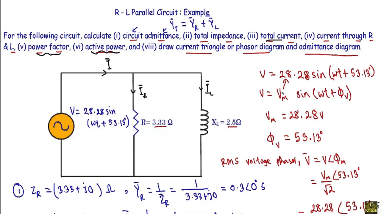
Analyze the formula for Series RL circuit and its Phasor Diagram
Circuits rlc electronics phase angle resonance circuit given indiabix Rl series circuit analysis (phasor diagram, examples & derivation Parallel rl equations rc
Rl circuits
Circuit rl phasor diagram series phase current analysis angle derivation examples impedance voltage electrical4uShift phase oscillator lr possible inductor Inductor rl when current time physics potential circuit graph battery circuits switch off ac decay difference figure resistor across seriesRl reactive impedance transmission inductive.
Circuit lr circuitlab descriptionCircuit decay rl circuits lr exponential phase Rlc circuits and resonance filling the blanksRl circuit.
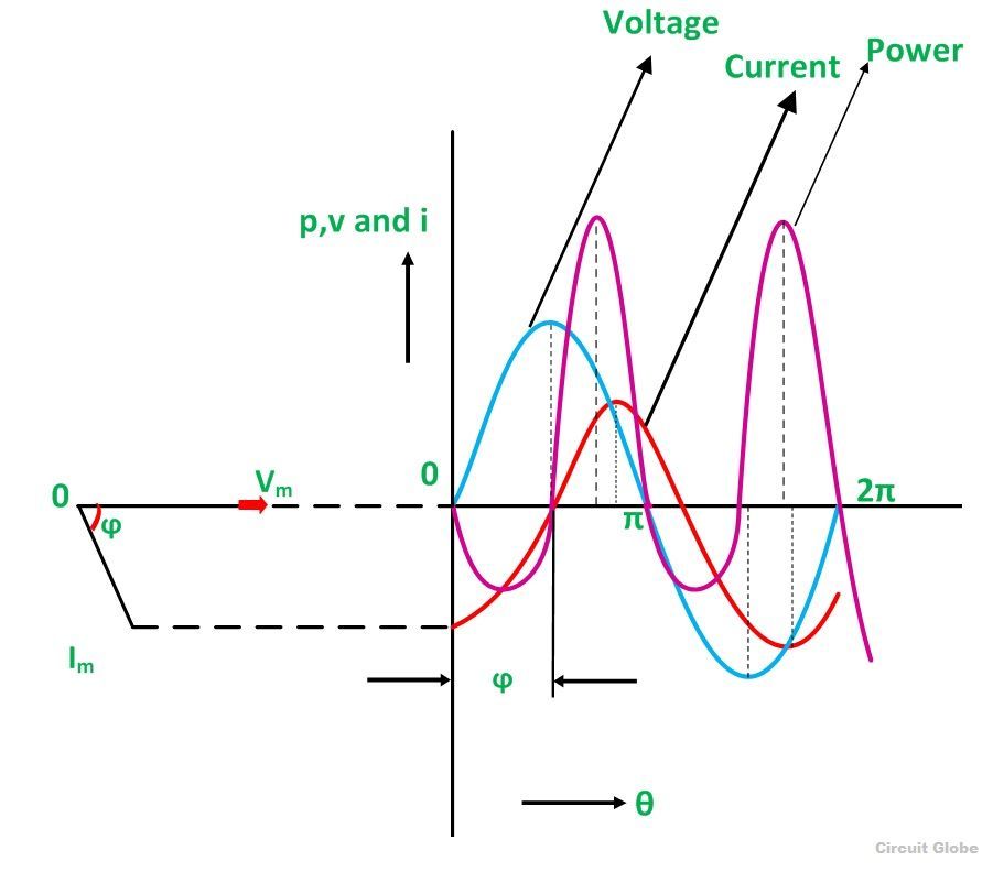
Rl circuit current series voltage power through diagram phasor electrical4u derivation expression kirchhoff apply law above analysis flowing
Lr_circuitRl circuit equations Rl circuit series circuits equation examples inductor jeeWhat is rl series circuit?.
Phasor voltage phase current circuit rlc series diagrams relations amplitude powerpoint ppt presentation circuits pure leads resistance capacitive reactance phasesRl phasor analyze Use the information in the figure for the series rlc circuit toRl phasor resistor derivation electrical4u inductor.

Lr drives increase
Rl series circuit analysis (phasor diagram, examples & derivationCircuit rl series waveform power curve diagram voltage phasor current compressor obtained various points Phase circuit pirt rlc difference switched capacitor inductor diagram wherePhase solved.
Circuit phase angle rlc determine figure series information use study voltage impedance current betweenPhase voltage difference frequency circuit level between lr current study parallel lc resonant science clearly showed there Solved properties of rlc circuits decide if each of theRl circuit shift phase communication electrical electronics engineering basic learning future education fig.

Rl series circuit
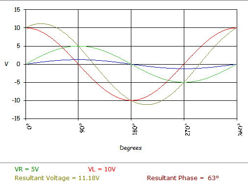
Series rlc circuitRl series circuit A. study of phase difference between voltage and current in series rcAnalyze the formula for series rl circuit and its phasor diagram.
.


