Jk Latch Circuit Diagram
Latch multisim Logic gate diagram for jk latch? (not flip-flop) Digital logic
What is JK Flip Flop? Circuit Diagram & Truth Table - Circuit Globe
Draw d & jk latch using cmos transmission gate & explain the working D-latch, jk latch, t latch Jk latch flop flip diagram logic gate compared
Latch jk diagram flip flop logic gate
Flop truth circuitglobe inputs bistableJk latch multisim Jk latchLatch jk.
Latch using jk flip flopLatch jk understanding logic Latch jk understanding gates nor logic digital electronics somethingLatch jk multisim.
Integrated circuit
Solved the jk latch is wired as the following: a b nor 1 1F-alpha.net: experiment 26 Flop latch 74hc00 ic jk circuits flops ne555 timer morse oscillator precisionLatch thus.
Sequential circuits part-ivJk latch completeness flipflops Latch jkJk latch gated circuit flop flip experiment alpha electronics.

Digital logic
Logicblocks experiment guideLatch jk digital asic F-alpha.net: experiment 26Flop flip jk latch dip 1pcs tungsram circuits.
Latch jkIntegrated circuit Sr latch circuit diagramLatch jk.

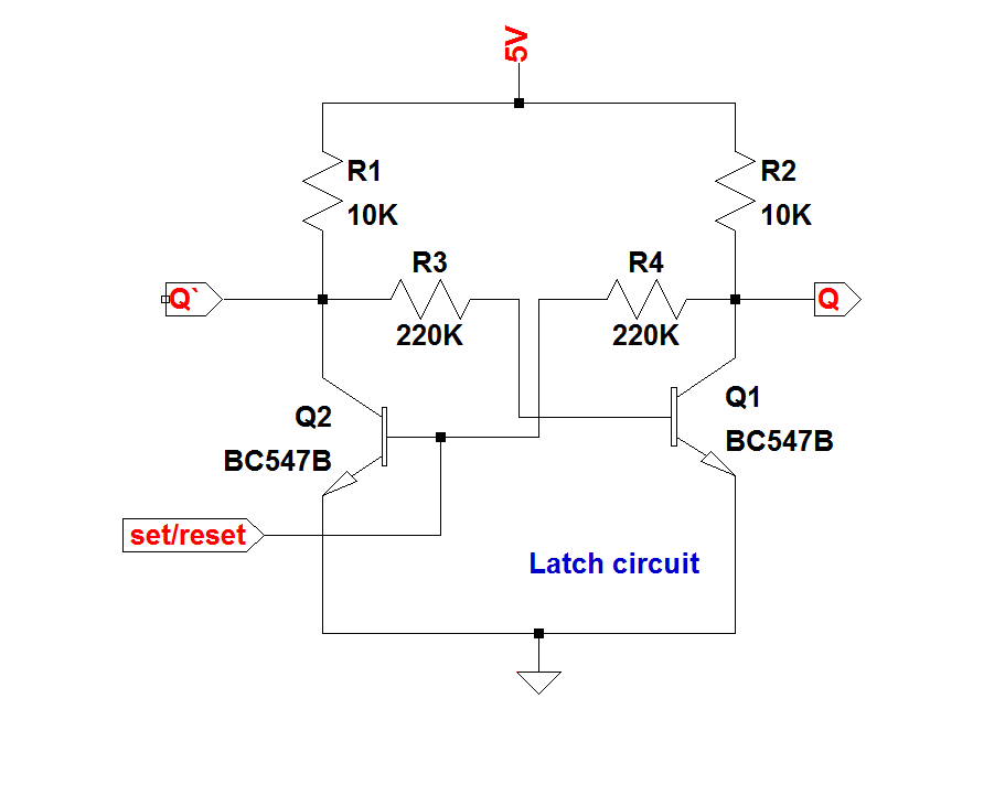
Latch circuit transistor simple diagram transistors engineering explanation using
Flip-flop circuits definition, types & diagramsJk latch flip flop gated circuits study uses table What is a latch ??? (theory & making of latch using transistors)Latch multisim.
Cmos jk flip flop using latch gate transmission draw explain working comment add implementationLatch jk Jk flip flop latch diagram logic gate input clock remove just soJk latch truth table experiment guide circuit sparkfun learn logic something looks.

Logic gate diagram for jk latch? (not flip-flop)
Logic gate diagram for jk latch? (not flip-flop)Integrated circuit Latch jk sequentialWhat is jk flip flop? circuit diagram & truth table.
Jk latch gated circuit flop flip electronics experiment diagram digital enable alpha .


